[ad_1]
To get started with Advent tinkering, we put the Nano-Ax-Board to work on a breadboard and equip it with the first components: an LED, a piezo buzzer and a button. This can be used to create a somewhat Christmas atmosphere. In our first program we let the LED flash like a candle with pulse width modulation and random values and play a pre-programmed song via the buzzer.
For all experiments on our Advent calendar, we use the 14-pin Picaxe-14M2 chip, which is attached to the Nano-Ax board (available exclusively in the Heise Shop). It has 12 pins that can be used as inputs or outputs: B.0 to B.5 and C.0 to C.5. These are the internal designations on the wiring diagram. The designations directly on the pin strips correspond to the footprint on the Nano-Ax board and identify the pins of a Picaxe-20M2, which can also be used with the board. The 5 volt power supply occurs (after setting up the circuit) via the USB connection of the board from the PC.
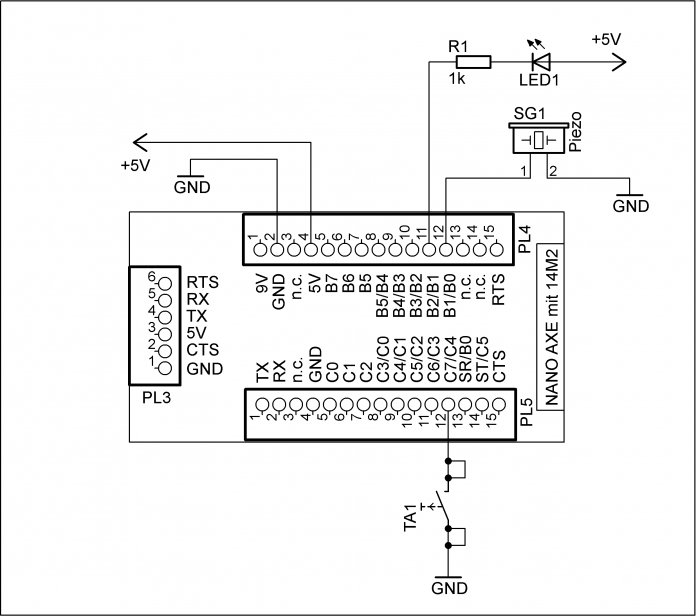
Circuit diagram for the 1st Advent
Four small doors instead of 24: with the Nano-Ax-Board we are building a brilliant and sound project for four Advent Sundays to participate in.
-
Program
-
First warning
Circuit design
Before we start, two more tips: first put the circuit together on the breadboard before connecting the board to the PC with a USB cable. It is also recommended to use a USB hub: in the event of a short circuit, the hub normally protects the PC from damage.
Sketch for the construction
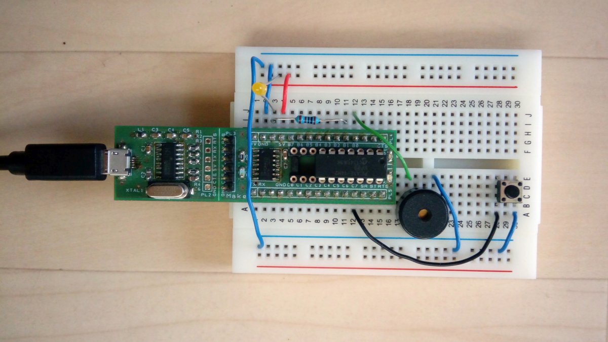
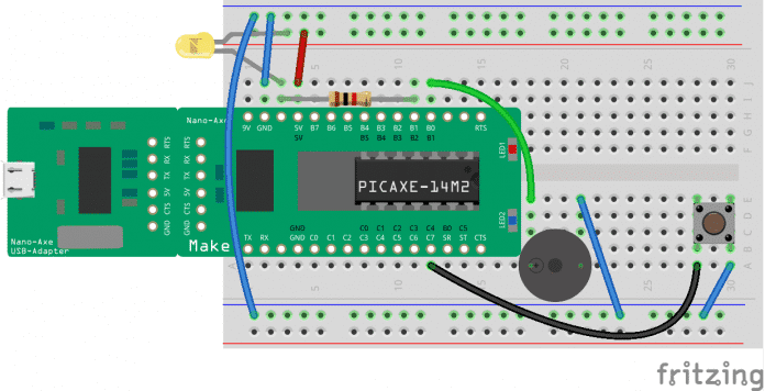
The yellow light diode (LED1) is connected with the resistor in series (R1) to pin B.2 of the Picaxe-14M2 (label B1 on the Nano-Ax board). It is not absolutely necessary because on this pin there is also the blue led of the board. If a LOW level is output at pin B.2 of the 14M2, both LEDs are then on. Since we want to simulate a flickering candle, the yellow color is better. For the audio output we use a small piezoelectric buzzer connected to pin B.1 (labeled B0) and GND. Finally we inserted a small button (pin C.4, labeled C7) and set it to GND. We activate the necessary pull-up resistor in the Picaxe firmware.


As we are gradually expanding the circuit next Sunday in Advent, it is advisable to wire the breadboard as shown. So there is enough space for the other components. We placed the 5V supply voltage that the Nano-Ax board supplies on the top row of the breadboard marked red. In the sketch, all the connecting wires inside the 5V plug-in board are shown in red. GND is present in the two lines marked in blue and the related connection wires are marked in blue.
.
[ad_2]
Source link
